Guillaume Vinet
|
0
|
May 13, 2026


The Time Travel Debugging tool provided by esReverse is powerful for firmware vulnerability research. By recording an execution and replaying it deterministically, you can inspect the exact moment a bug triggers, step backward through the call stack, and understand the full exploitation path without having to reproduce the conditions from scratch.
The catch is that embedded firmware often relies on peripherals that QEMU does not emulate. When that happens, the execution path you need to analyze is simply unreachable, and you are left with alternatives like Unicorn or Qiling. These are valid tools, but they come with their own limitations. It is a shame to give up on QEMU simply because some peripherals are missing.
This post demonstrates that it's not a problem. We show how to identify a missing peripheral, add it to QEMU, and unlock full-system Time Travel Analysis (TTA), made possible by the Time Travel Debugging tool, on a real, unmodified firmware image.
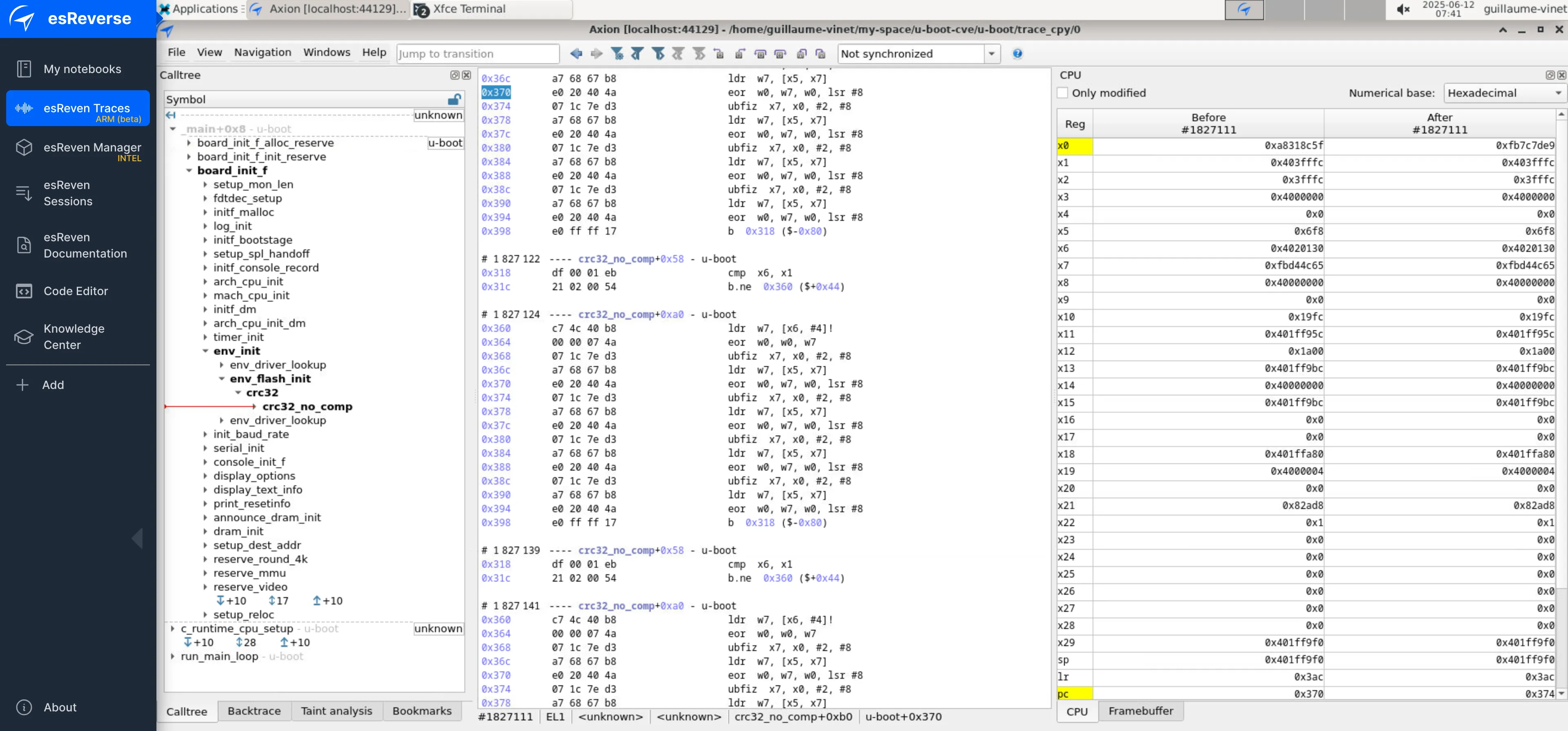
In our previous post, we compiled the secure bootloader U-Boot specifically for a QEMU ARM64 target. Emulation worked perfectly, and we were able to perform TTA (Time Travel Analysis) to analyze CVE-2019-14192, a buffer overflow in U-Boot’s NFS client triggered by a malicious server returning a forged length field in a NFS readlink response.
That scenario had one comfortable assumption: we had the sources and could compile the firmware for a QEMU target. In the real world, this is rarely the case. You typically have a binary firmware compiled for a specific hardware board. The board may not be supported by QEMU, and without sources there is no way to recompile for a QEMU target. If a required peripheral is missing from the emulation, the execution path you need to analyze is simply unreachable.
The question is: what does it actually take to add that missing peripheral? To find out, we keep the same objective: we want to perform a TTA of CVE-2019-14192 affecting U-Boot, but this time using firmware compiled for a real board — the Raspberry Pi 3B+. We will see that a driver is missing from QEMU's implementation, and that adding it is possible.
We use the same setup as previously, with U-Boot version 2019.07, the only difference being the compilation target (please refer to the previous blog post for the full setup details).
This time we compile U-Boot for a Raspberry Pi 3B Model B+ (hereafter referred to as R3B+) using this command:
make rpi_3_b_plus_defconfigWe obtain the U-boot firmware to emulate: u-boot.bin. Then, we start the QEMU emulation using the R3B+ board support:
qemu-system-aarch64 -M raspi3b -kernel ./u-boot.bin -serial null -serial mon:stdio -nographic -no-rebootThe main options here are:
-M raspi3b: we select the Raspberry Pi 3B machine model.-kernel ./u-boot.bin: we load the compiled U-Boot firmware binary.-serial null: we discard the first UART.-serial mon:stdio: we redirect the second UART to the terminal.-nographic: we disable the graphical display; all input/output goes through the terminal (serial console).-no-reboot: we prevent QEMU from automatically rebooting when the guest system shuts down or crashes.The U-Boot boot log immediately reveals the problem:
MC:   mmc@7e202000: 0, sdhci@7e300000: 1
Card did not respond to voltage select!
In:    serial
Out:   vidconsole
Err:   vidconsole
Net:   No ethernet found.
starting USB...
Bus usb@7e980000: scanning bus usb@7e980000 for devices... 1 USB Device(s) found
       scanning usb for storage devices... 0 Storage Device(s) found
Hit any key to stop autoboot:  0
U-Boot>
Two details stand out here:
First, the line Net: No ethernet found indicates that U-Boot scanned for a network interface and found nothing.
Second, the USB bus reports only 1 device.
So the Ethernet interface is missing, which means we cannot reach the NFS stack, which means CVE-2019-14192 cannot be triggered, which means TTA is blocked. Is that the end of the road? Not quite… that would make for a rather short blog post. The plan is to identify exactly which peripheral is missing, then add it to QEMU ourselves.
There are several ways to identify which driver is missing.
One approach is to load the code on a real Raspberry Pi board. There are two useful commands in U-Boot for getting information about hardware:
First, dm tree displays the U-Boot driver model device tree, showing which drivers are bound and active. Then, usb info lists all USB devices detected on the bus with their vendor ID, product ID, and endpoint (EP) configuration.
We first run these commands on the QEMU-emulated board:
U-Boot> dm tree
// [...]
 usb          0  [ + ]   dwc2_usb              |   `-- usb@7e980000
 usb_hub      0  [ + ]   usb_hub               |       `-- usb_hub
 simple_bus   1  [   ]   generic_simple_bus    `-- clocks

U-Boot> usb info
1: Hub,  USB Revision 1.10
 -  U-Boot Root Hub
 - Class: Hub
 - PacketSize: 8  Configurations: 1
 - Vendor: 0x0000  Product 0x0000 Version 0.0
   Configuration: 1
   - Interfaces: 1 Self Powered 0mA
     Interface: 0
     - Alternate Setting 0, Endpoints: 1
     - Class Hub
     - Endpoint 1 In Interrupt MaxPacket 2 Interval 255ms
And, then on the R3B+ board:
U-Boot> dm tree
// [...]
 blk          1  [   ]   mmc_blk               |   |   `-- sdhci@7e300000.blk
 video        0  [ + ]   bcm2835_video         |   |-- hdmi@7e902000
 vidconsole   0  [ + ]   vidconsole0           |   |   `-- hdmi@7e902000.vidconsole0
 usb          0  [ + ]   dwc2_usb              |   `-- usb@7e980000
 usb_hub      0  [ + ]   usb_hub               |       `-- usb_hub
 usb_hub      1  [ + ]   usb_hub               |           `-- usb_hub
 eth          0  [ + ]   smsc95xx_eth          |               `-- smsc95xx_eth
 simple_bus   1  [   ]   generic_simple_bus    `-- clocks
U-Boot> usb info
// [...]
3: Vendor specific,  USB Revision 2.0
 - Class: Vendor specific
 - PacketSize: 64  Configurations: 1
 - Vendor: 0x0424  Product 0xec00 Version 2.0
   Configuration: 1
   - Interfaces: 1 Self Powered Remote Wakeup 2mA
     Interface: 0
     - Alternate Setting 0, Endpoints: 3
     - Class Vendor specific
     - Endpoint 1 In Bulk MaxPacket 512
     - Endpoint 2 Out Bulk MaxPacket 512
     - Endpoint 3 In Interrupt MaxPacket 16 Interval 4ms
From this comparison, we can identify the missing device: a SMSC LAN9514 USB Ethernet adapter, VID:PID 0x0424:0xec00, driven by the smsc95xx driver.
This is confirmed by two additional sources. The R3B+ documentation is fully open: it shows that Ethernet is provided by a SMSC LAN9514 chip connected to the SoC via USB rather than a dedicated MAC, which is why it appears as a USB device and requires a USB Ethernet driver. On the software side, the U-Boot board configuration for the Raspberry Pi 3B explicitly lists smsc95xx as a dependency, and drivers/usb/eth/smsc95xx.c confirms the supported USB IDs. This file will also prove invaluable when implementing the QEMU driver: it describes precisely how the hardware behaves, register by register.
We now know what is missing. The next step is to add it to QEMU.
Fortunately, QEMU is fully open source, which means we can modify it to add whatever peripheral we need.
In this post, we use the following QEMU version:
git clone https://gitlab.com/qemu-project/qemu.git
cd qemu
git checkout d8a9d97317d03190b34498741f98f22e2a9afe3e
git submodule update --init --recursive
Adding a new device involves three distinct steps:
First, we need to create the file that implements the Ethernet driver. The easiest approach is to start from an existing QEMU device that is close enough to what we need and adapt it, rather than writing everything from scratch.
Second, we need to tell the Raspberry Pi 3B board that this device exists. This means modifying QEMU's board source code (hw/arm/raspi.c) to instantiate and attach the device at startup, and updating the QEMU command line accordingly.
Finally, at this point the device will be present in the emulation, but its behavior will be wrong or empty. We will need to understand what U-Boot's SMSC95xx driver actually expects from the hardware, and implement it step by step until U-Boot recognizes the device and can use it for networking.
Let's go through each of these steps.
In our previous post, we ran U-Boot compiled for QEMU using the virt machine with a virtio-net-device for networking:
qemu-system-aarch64 \
    -M virt \
    -cpu cortex-a57 \
    -smp 1 \
    -m 512M \
    -nographic \
    -bios ./u-boot.bin \
    -netdev user,id=net0 \
    -device virtio-net-device,netdev=net0 \
    -no-reboot
The -netdev user,id=net0 option enables QEMU's built-in user-mode network stack, also known as slirp. It requires no special privileges and no host network configuration: slirp acts as a lightweight NAT, providing the guest with a virtual network (10.0.2.0/24), a default gateway (10.0.2.2), and a built-in DHCP server that automatically assigns 10.0.2.15 to the guest.
The -device virtio-net-device is implemented in QEMU's source tree. It is a good starting point, implemented in hw/net/virtio-net.c. We make a copy in hw/usb/dev-smsc95xx.c.
Then we register it in the build system by adding one line to hw/usb/meson.build:
softmmu_ss.add(files('dev-smsc95xx.c'))
The first approach that comes to mind is to modify the Raspberry Pi board code in hw/arm/raspi.c to instantiate and attach the device to the USB bus at machine startup. This works, but it raises several practical questions: at which USB address should the device be attached? Behind which hub? At which point in the initialization sequence? Getting these details wrong silently breaks USB enumeration, and debugging it is painful.
A simpler approach avoids touching the board code entirely. QEMU maintains a global device registry: when dev-smsc95xx.c is compiled in, the type_init macro registers the "usb-smsc95xx" type at startup, before any machine is initialized. This means we can simply declare the device on the command line and let QEMU handle the attachment:
qemu-system-aarch64 -M raspi3b -kernel ./u-boot.bin \
    -serial null -serial mon:stdio -nographic \
    -device usb-smsc95xx,netdev=net0,bus=usb-bus.0 \
QEMU will plug the device into the USB bus. U-Boot will discover it during its USB scan, provided of course that the driver implementation is correct enough for U-Boot to recognize and probe it. That is precisely what we tackle in the next step.
virtio-net.c is a large, feature-rich file (~4300 lines). We don’t need most of it. What we actually reuse is the netdev plumbing pattern - the three elements that connect any QEMU network device to the host network stack:
// 1. A NICState and NICConf in the device state struct
NICState *nic;
NICConf   conf;

// 2. A NetClientInfo struct declaring the receive callback
static NetClientInfo smsc95xx_net_info = {
    .type    = NET_CLIENT_DRIVER_NIC,
    .size    = sizeof(NICState),
    .receive = smsc95xx_receive,
    .cleanup = smsc95xx_cleanup,
};

// 3. qemu_new_nic() in the realize function
s->nic = qemu_new_nic(&smsc95xx_net_info, &s->conf, ...);
Everything else - the virtio ring buffers, the feature negotiation, the migration state - is discarded. The file structure is also reused: includes, state struct, realize/unrealize, class_init, type registration via type_init. This skeleton, stripped of virtio-specific code, is the foundation of dev-smsc95xx.c.
The key insight is that drivers/usb/eth/smsc95xx.c in U-Boot tells us exactly what our emulated device must do. Every function in that file describes a real exchange with the chip.
We instrument our QEMU driver with warn_report() to log every interaction in real time:
warn_report("smsc95xx: %s %s bReq=0x%02x reg=%-12s (0x%03x) len=%d",
            dir, type, bRequest, smsc95xx_reg_name(index), index, length);
This gives us a live trace of every register read and write that U-Boot performs, printed directly in the QEMU terminal. Combined with reading the U-Boot source, we can match each log line to the exact line of code that produced it.
The first goal is simply to make U-Boot’s USB scan find the device. In QEMU’s device model, a USB device is described by a hierarchy of static structures. At the top sits a USBDesc that carries the VID/PID and points to the device descriptors for each supported speed. Each USBDescDevice contains a USBDescConfig, which in turn references a USBDescIface listing the endpoints:
static const USBDesc smsc95xx_desc = {
    .id = {
        .idVendor  = 0x0424,   // SMSC
        .idProduct = 0xec00,   // LAN9512/LAN9514
        ...
    },
    .full  = &smsc95xx_device_full,   // Full Speed (12 Mbps)
    .high  = &smsc95xx_device_high,   // High Speed (480 Mbps)
};
We declare two variants: Full Speed and High Speed. Indeed, the maximum packet size for bulk endpoints differs between them: 64 bytes vs 512 bytes. Each variant lists the same three endpoints:
static const USBDescIface smsc95xx_iface_full = {
    .bNumEndpoints = 3,
    .eps = (USBDescEndpoint[]) {
        { .bEndpointAddress = USB_DIR_IN  | 0x01,   // EP1 Bulk IN  - RX packets
          .bmAttributes     = USB_ENDPOINT_XFER_BULK,
          .wMaxPacketSize   = 64  },
        { .bEndpointAddress = USB_DIR_OUT | 0x02,   // EP2 Bulk OUT - TX packets
          .bmAttributes     = USB_ENDPOINT_XFER_BULK,
          .wMaxPacketSize   = 64  },
        { .bEndpointAddress = USB_DIR_IN  | 0x03,   // EP3 Interrupt IN - status
          .bmAttributes     = USB_ENDPOINT_XFER_INT,
          .wMaxPacketSize   = 16  },
    },
};
The three-endpoint requirement is not immediately obvious. Reading U-Boot’s probe function reveals it:
// drivers/usb/eth/smsc95xx.c
if (!ss->ep_in || !ss->ep_out || !ss->ep_int)
    return 0;   /* device rejected silently */
Without the interrupt endpoint (EP3), ss->ep_int is NULL and the device is rejected with no error message. Once all three are declared, U-Boot finds and probes the device successfully:
Now that U-Boot detects the device, it moves on to initialization. This is where the real implementation work begins, and where reading U-Boot source code becomes the most valuable tool we have.
The central function is smsc95xx_init_common in drivers/usb/eth/smsc95xx.c. It is the complete initialization sequence for the chip, and reading it carefully tells us everything our emulated device must do. It communicates with the hardware exclusively through two generic helper functions:
smsc95xx_write_reg(udev, reg, val): it sends a USB vendor control request (bmRequestType=0x40, bRequest=0xA0) to write a 32-bit value into a chip registersmsc95xx_read_reg(udev, reg, &val): it sends the corresponding read request (bmRequestType=0xC0, bRequest=0xA1) and returns the current register valueEvery register access in smsc95xx_init_common goes through these two functions. This means that on the QEMU side, all of them land in a single function: smsc95xx_handle_control. This function is registered as the handle_control callback in USBDeviceClass during class_init, so QEMU routes every USB control transfer to it automatically:
static void smsc95xx_class_init(ObjectClass *klass, const void *data)
{
    USBDeviceClass *uc = USB_DEVICE_CLASS(klass);
    uc->handle_control = smsc95xx_handle_control;  // all control transfers land here
    uc->handle_data    = smsc95xx_handle_data;
    ...
}
Inside smsc95xx_handle_control, we decode the request type, read or write, and dispatch on the register index. This is also where we implement the hardware side effects that smsc95xx_init_common expects.
And there are several. The function performs a long sequence of register writes followed by polling loops that wait for specific bits to clear. Without those side effects, U-Boot loops forever.
The warn_report trace makes each hang immediately visible: - the same register read repeats endlessly - and smsc95xx_init_common tells us exactly what the hardware is supposed to do in response:
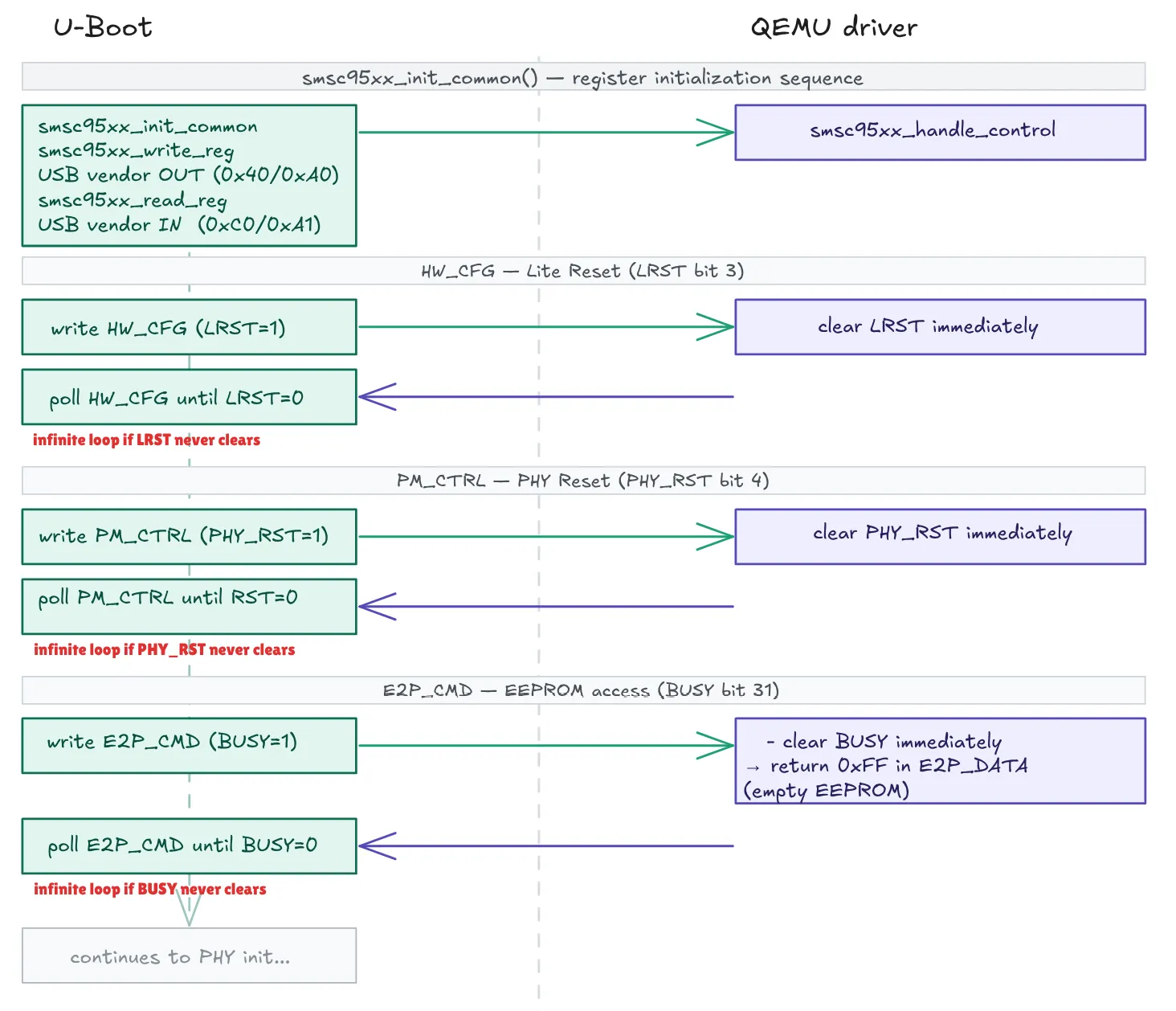
Each side effect is implemented directly in smsc95xx_handle_control, immediately after storing the written value:
if (index == SMSC95XX_HW_CFG)
    s->regs[SMSC95XX_HW_CFG / 4] &= ~0x00000008;   // clear LRST

if (index == SMSC95XX_PM_CTRL)
    s->regs[SMSC95XX_PM_CTRL / 4] &= ~0x00000010;  // clear PHY_RST

if (index == SMSC95XX_E2P_CMD && (val & 0x80000000)) {
    s->regs[SMSC95XX_E2P_DATA / 4] = 0xFF;
    s->regs[SMSC95XX_E2P_CMD  / 4] &= ~0x80000000; // clear BUSY
}
This pattern - spot the hang in the trace, find the corresponding poll loop in smsc95xx_init_common(), implement the side effect - repeats for each register in the sequence. It is mechanical but effective, and smsc95xx_init_common is the map that guides every step.
After the reset sequence, U-Boot checks the PHY link state by reading MII registers through MII_ADDR/MII_DATA. The critical register is MII_BMSR (PHY register 1): if bit 2 (BMSR_LSTATUS) is not set, U-Boot prints unable to connect after a 5-second timeout.
A subtle bug here: we initially triggered the MII handler only when the BUSY bit was set in the written value. But the BUSY bit is set by the hardware, not by U-Boot - U-Boot just writes the address and direction. The fix is to trigger on any write to MII_ADDR, unconditionally:
if (index == SMSC95XX_MII_ADDR) {
    uint8_t phy_reg = (val >> 6) & 0x1F;
    uint8_t is_read = !(val & 0x02);

    if (is_read) {
        switch (phy_reg) {
        case 1:  mii_val = 0x782D; break;  // BMSR: link up + auto-neg complete
        case 0:  mii_val = 0x3100; break;  // BMCR: auto-neg enabled
        case 4:  mii_val = 0x01E1; break;  // ADVERTISE
        default: mii_val = 0x0000; break;
        }
        s->regs[SMSC95XX_MII_DATA / 4] = mii_val;
    }
    s->regs[SMSC95XX_MII_ADDR / 4] &= ~0x01;  // clear BUSY immediately
}
The log trace shows U-Boot moving past the PHY check and printing Waiting for Ethernet connection… - confirming link up is accepted.
With the link up, U-Boot issues a dhcp command. This triggers the actual network traffic path - sending and receiving Ethernet frames over the USB bulk endpoints.
In QEMU’s USB device model, bulk transfers are routed through a single callback registered in USBDeviceClass during class_init:
static void smsc95xx_class_init(ObjectClass *klass, const void *data)
{
    USBDeviceClass *uc = USB_DEVICE_CLASS(klass);

    uc->handle_control = smsc95xx_handle_control;  // vendor register r/w
    uc->handle_data    = smsc95xx_handle_data;     // bulk IN/OUT transfers
    uc->handle_reset   = smsc95xx_handle_reset;    // USB reset
    uc->realize        = smsc95xx_realize;         // device creation
    ...
}
handle_data is called by QEMU whenever U-Boot performs a bulk transfer on any endpoint. It dispatches to the appropriate function based on the endpoint number ():
static void smsc95xx_handle_data(USBDevice *dev, USBPacket *p)
{
    switch (p->ep->nr) {
    case 1: smsc95xx_handle_data_in(s, p);  break;  // RX: network → U-Boot
    case 2: smsc95xx_handle_data_out(s, p); break;  // TX: U-Boot → network
    default: p->status = USB_RET_STALL;     break;
    }
}
On the network side, incoming packets from slirp arrive via smsc95xx_receive, which is registered as a callback in NetClientInfo and connected to the netdev backend during realize:
static NetClientInfo smsc95xx_net_info = {
    .receive = smsc95xx_receive,   // called by slirp when a packet arrives
};

// in smsc95xx_realize():
s->nic = qemu_new_nic(&smsc95xx_net_info, &s->conf, ...);
The two paths are fundamentally asymmetric:
smsc95xx_receive, which queues the packet, and U-Boot then comes to fetch it by polling EP1. If the queue is empty, handle_data_in replies USB_RET_NAK (nothing yet). usb_wakeup is called after queuing to signal that data is available and prompt QEMU to deliver it sooner.Several non-obvious details had to be handled correctly on each path.
TX — Full Speed fragmentation. At Full Speed (12 Mbps), QEMU delivers bulk OUT transfers in 64-byte chunks. A 350-byte DHCP packet arrives as 6 separate calls to handle_data_out(). Without a reassembly buffer, the first chunk would be forwarded immediately as an incomplete frame. We accumulate chunks in tx_buf and only forward to qemu_send_packet() once the complete frame has arrived:
usb_packet_copy(p, s->tx_buf + s->tx_buf_len, chunk);
s->tx_buf_len += chunk;

if (s->tx_buf_len >= s->tx_pkt_len + 8) {
    qemu_send_packet(qemu_get_queue(s->nic), s->tx_buf + 8, s->tx_pkt_len);
    s->tx_buf_len = 0;
    s->tx_pkt_len = 0;
}
TX — Wrong length mask. The frame length is in bits [10:0] of tx_cmd_a, per the LAN9514 datasheet. The initial mask 0x000FFFFF also captured flag bits 12 and 13 (FIRST_SEG, LAST_SEG), producing a wildly incorrect length. The correct mask is 0x7FF:
#define TX_CMD_A_LEN_MASK 0x000007FFRX — Status word and FCS. The SMSC RX format wraps each frame with a 4-byte status word and 4 dummy FCS bytes. U-Boot validates the packet with:
packet_len = (rx_status & 0x3FFF0000) >> 16;
if (packet_len > actual_len - 4)
    return -EIO;
actual_len is the total number of bytes received over USB. For this check to pass, the packet_len field in the status word must equal size + 4, and the USB transfer must include the 4 FCS bytes — both must be consistent:
rx_sts = (uint32_t)((size + 4) << 16) & 0x3FFF0000;
// ... frame data ...
slot[4 + size + 0..3] = 0;              // 4 dummy FCS bytes
s->rx_queue[s->rx_tail].len = size + 8; // status + frame + FCS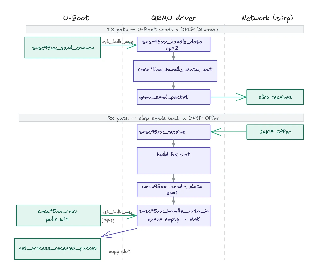
With these modifications in place, QEMU can be recompiled:
mkdir build && cd build
../configure --target-list=aarch64-softmmu  --enable-slirp --prefix=/usr/local
make -j4
The emulation can then be launched with our new device attached to the USB bus. U-Boot will detect it during its USB scan and use it to bring up the network interface.
qemu-system-aarch64 -M raspi3b -kernel ./u-boot.bin \
    -device usb-smsc95xx,netdev=net0,bus=usb-bus.0 \
    -netdev user,id=net0,hostfwd=tcp::2222-:22 \
    -no-reboot
With both paths correctly implemented, the result is immediate:
U-Boot> dhcp
DHCP client bound to address 10.0.2.15 (9 ms)

U-Boot> ping 10.0.2.2
host 10.0.2.2 is alive
We can reuse the same python scripts as in the previous blog post, and it works perfectly: we manage to retrigger the flaw. The implementation is a success!!!
Adding a missing peripheral to QEMU is often more approachable than it looks.
We demonstrated this by implementing the USB over ethernet adapter missing from QEMU’s Raspberry Pi 3B+ emulation. It was preventing the TTA analysis of the CVE-2019-14192 affecting U-Boot compiled for this board.
Having access to the U-Boot source code was a significant advantage here: it gave us a precise specification of the hardware behaviour without needing a logic analyzer or a datasheet for every detail. With a pure binary and no sources, the same approach would still be possible, but more tedious.


